Geology Faculty and Staff
The University of South Alabama is about unlimited possibilities, unexpected experiences, unbelievable accomplishments and unique personalities. USA is about who you want to be, what you want to achieve and where you want to go. At USA, you’ll find the people, resources and support to start you on your path to earning a college degree.
| Name | Contact Information | Categories | Index |
|---|---|---|---|
| Allison, David, Ph. D. Associate Professor of Geology 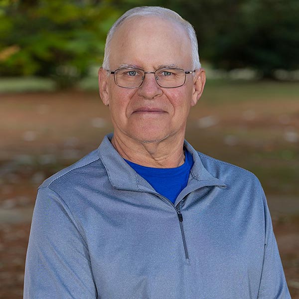
|
Office: ELSB 049 (251) 460-7574 dallison@southalabama.edu |
geology | A |
|
Beebe, Alex, Ph. D.
Professor of Geology 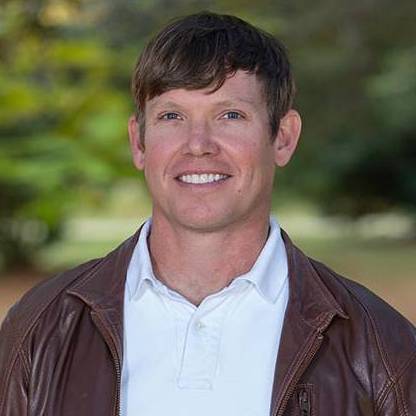
|
Office: ELSB 344 (251) 460-7569 dbeebe@southalabama.edu |
geology | B |
| Clark, Murlene, Ph. D. Associate Professor Emeritus of Geology 
|
(251) 460-7570 mclark@southalabama.edu |
geology, emeritus | C |
|
Haywick, Doug, Ph. D.
Associate Professor Emeritus of Geology 
|
(251) 460-6381 dhaywick@southalabama.edu |
geology, emeritus | H |
| Hillard, Maureen, Ph. D. Geology/Geography and Geographic Information Systems Instructor 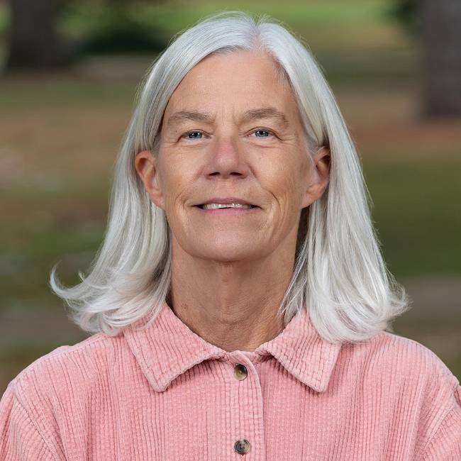
|
m.hillard@southalabama.edu | geology, adjunct | H |
| Isphording, Wayne, Ph. D. Professor Emeritus of Geology 
|
(251) 460-6381 | geology, retired | I |
|
Linzmeier, Benjamin, Ph. D.
Assistant Professor of Geology 
|
Office: ELSB 343(251) 460-7575blinzmeier@southalabama.edu | geology | L |
| Yokel, Lee, M.S. Geology Instructor 
|
Office: ELSB 341 (251) 460-7570 lyokel@southalabama.edu |
geology, adjunct | Y |